Traction Converter Core Components: Roles in Locomotive Power Conversion





A locomotive traction converter cannot be evaluated by its megawatt rating alone. Its usable performance depends on how the input stage, DC link, power semiconductors, control electronics, and cooling system behave together during acceleration, wheel slip, supply disturbances, and electrical braking. Two converters with similar nameplate ratings can have materially different overload capability, motor compatibility, and fault-recovery behavior.
The term traction converter core is best understood as the functional power-conversion assembly rather than a single component or universally standardized package. Its boundaries vary by supplier: some assemblies include input converters and braking choppers, while others refer mainly to inverter modules and their controls. A meaningful evaluation therefore starts with the electrical architecture and the operating conditions attached to every rating.
The input architecture determines what the converter must do
In an AC-fed electric locomotive, the traction transformer reduces the overhead-line voltage and provides secondary supplies to the line-side converters. An actively controlled input converter can regulate the DC-link voltage, shape input current, and return braking energy to the supply when the infrastructure permits. The transformer is upstream of the power-electronic conversion stage, but its leakage impedance and secondary arrangement directly affect converter control and fault behavior.
A DC-fed locomotive receives power without that AC transformer stage. Depending on supply voltage and system design, the input path may include line reactors, filters, contactors, and a DC–DC conversion stage before the traction inverter. Supply-voltage variation and line transients must be accommodated without exceeding semiconductor or capacitor limits.
In a diesel-electric locomotive with AC traction motors, the alternator output is rectified to establish the DC link. A diode rectifier has no independently commanded switching action: DC-link voltage depends on alternator output, excitation control, loading, and circuit impedance. Dynamic-braking energy cannot simply pass backward through this rectifier into the engine; it requires another destination, commonly a resistor grid.
These distinctions prevent a common specification error: requiring identical rectifier functions across incompatible architectures. Regenerative capability belongs to the complete power path, not merely to an inverter advertised as bidirectional.
Input converters and the DC link: controlling the energy balance
An active line-side converter does more than turn AC into DC. It coordinates current drawn from the source with energy demanded by the traction inverters, while keeping the intermediate voltage within its operating band. On AC railway supplies, performance must be assessed against the relevant network impedance and disturbance conditions. Stable operation on an ideal laboratory source does not establish compatibility with a railway feeding system.
Input reactors and filters limit current ripple and help manage conducted interference. Their interaction with transformer leakage, line impedance, and converter control can introduce resonances. Filter design therefore requires both electrical-network analysis and control-loop assessment; adding capacitance is not automatically an improvement.
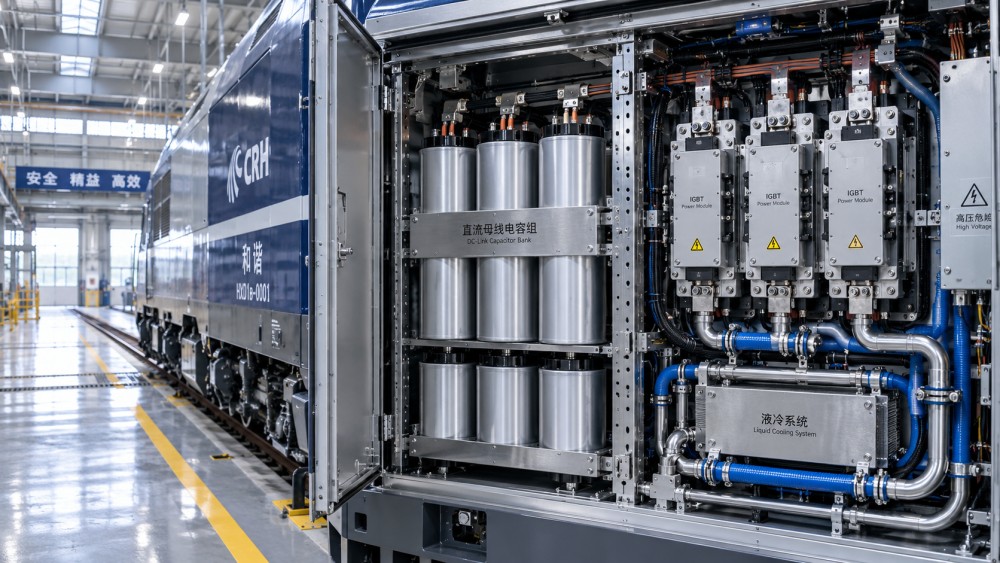
The DC-link capacitor bank buffers the instantaneous difference between input and motor-side power. Its stored energy follows E = ½CV², but energy capacity alone is an incomplete selection criterion. Capacitors also carry ripple current, and internal losses raise their temperature. The required capacitance, RMS ripple-current capability, voltage margin, and lifetime must all correspond to the actual duty cycle.
Capacitor deterioration can increase equivalent series resistance or reduce capacitance, changing both heating and voltage ripple. Lifetime estimates should use the capacitor’s own operating temperature and loading assumptions, not only ambient air temperature. Film-capacitor and electrolytic-capacitor designs have different characteristics; neither should be accepted solely on technology name.
Precharge circuits limit inrush when the DC link is energized. Their resistors, switching devices, and monitoring logic must withstand the specified start frequency and detect unsuccessful charging. Discharge arrangements serve a different purpose: bringing stored voltage down after isolation. A commanded shutdown is not proof that the assembly is safe to touch, so maintenance procedures need a defined discharge interval and voltage-verification method.
Traction inverters: turning DC power into controlled torque
The motor-side inverter synthesizes variable-frequency, variable-voltage AC from the DC link. Torque depends on the interaction between that output and the motor’s electromagnetic state, not simply on inverter output frequency. Induction-motor and permanent-magnet-motor drives therefore require control strategies suited to their respective machines.
At low speed, high tractive effort can demand substantial current even when mechanical power is modest. At higher speed, available motor voltage becomes a constraint, and field-weakening operation may be required. A continuous-power figure does not describe this entire envelope. Current limits, DC-link voltage, modulation capability, motor parameters, and thermal limits determine the usable torque–speed range.
Two-level and multilevel inverter arrangements distribute voltage stress and generate output waveforms differently. A multilevel topology can reduce individual voltage steps and alter filtering requirements, but it also introduces additional devices, control states, or voltage-balancing obligations. Its value must be judged at the intended voltage and duty rather than from topology alone.
Motor grouping is another consequential choice. Individual inverter control provides electrical control at each associated motor or axle, subject to the mechanical arrangement. Multiple motors connected to one inverter share an electrical output, limiting how independently their torque can be adjusted. This affects adhesion control, isolation strategy, and the traction available after a fault.
Semiconductors and gate drivers set the switching limits
Silicon IGBTs and silicon-carbide MOSFETs offer different conduction and switching characteristics. SiC devices can enable lower switching losses or higher switching frequency in a suitable design, but the benefit depends on voltage class, current, modulation, packaging, and cooling. A device-level efficiency advantage should not be treated as a guaranteed reduction in complete-locomotive energy consumption.
Faster switching also increases the importance of parasitic inductance, electromagnetic interference, insulation stress, and motor-cable behavior. Voltage overshoot is influenced by switching speed and the power-loop inductance. Reflected voltage waves along motor cables can create terminal stresses beyond those suggested by the nominal DC-link voltage.
Low-inductance busbars, appropriate module placement, gate-drive tuning, and any necessary output filtering must therefore be evaluated together. Slowing a switching edge may reduce stress and interference while increasing switching loss. This is an engineering trade-off, not simply a matter of using the fastest available semiconductor.
The gate driver is the interface between low-power control and high-power switching. It supplies gate charge, maintains isolation, and supports device-specific protection. For IGBT stages, desaturation detection is one established method of detecting certain short-circuit conditions; other devices and architectures may use different approaches.
Protection timing matters because the permissible response window is device-specific. The delay through sensing, logic, gate drive, and controlled turn-off must fit within the applicable withstand limits. Dead time also needs careful setting: insufficient dead time risks simultaneous conduction, while excessive dead time distorts output voltage, particularly where commanded voltage is small.
Cooling determines whether rated performance is repeatable
Semiconductor losses become heat that must pass through the module package, thermal interface, cooling plate or heat sink, and finally the coolant or air stream. A low coolant temperature does not guarantee a low semiconductor junction temperature if another part of that thermal path has high resistance.
Liquid cooling permits compact power assemblies, but it brings requirements for flow control, coolant chemistry, electrical isolation where relevant, leak detection, and service access. Air cooling avoids a liquid circuit but requires adequate airflow under realistic filter condition, dust exposure, and installation pressure drop. Neither method can be judged independently of the locomotive enclosure and maintenance environment.
Continuous climbing, repeated acceleration, and prolonged electrical braking produce different thermal profiles. Braking changes the current paths and device-loss distribution; components that remain acceptable during motoring may experience different stress during regeneration or rheostatic braking. Thermal verification should therefore cover both directions of power flow.
Temperature cycling also matters. Repeated expansion and contraction can fatigue semiconductor interconnections, solder layers, and other interfaces. An overload rating needs its initial temperature, duration, repetition interval, and recovery conditions stated. Without these, it is impossible to determine whether the advertised overload can be used repeatedly in service.
Sensing, protection, and braking must act as one system
Current, voltage, speed, and temperature measurements support both control and protection. Sensor bandwidth, offset, isolation, and diagnostic coverage influence performance. A biased current measurement can compromise torque control, while delayed or failed temperature feedback can undermine thermal protection. Plausibility checks and defined responses to missing or inconsistent signals are therefore important design features.
During electrical braking, energy flows from the motors into the DC link. It must then return to a receptive supply, enter an energy-storage system, or be dissipated in a braking resistor. If none of these paths can accept the power, DC-link voltage rises and electrical braking must be limited.
A braking chopper switches energy into the resistor circuit when its control conditions are met. Its current rating, switching losses, resistor thermal capacity, and duty limit must be coordinated with the required braking profile. Resistor protection should not be confused with guaranteed braking availability: mechanical-brake coordination remains a vehicle-level responsibility.
Fault protection should distinguish semiconductor short circuits, motor-side faults, insulation faults, cooling failures, and upstream supply disturbances. Removing gate commands can stop switching, but it does not physically isolate every energy source. Isolation depends on the topology and the coordinated operation of contactors, circuit breakers, fuses, or other protective devices.
The useful reliability question is not simply whether a fault is detected. It is whether the converter contains the damage, identifies the affected section, reaches a safe state, and preserves permitted degraded operation. Fault records need enough time resolution and context to distinguish initiating events from consequential alarms.
Standards provide a framework, not a complete acceptance case
IEC 61287-1 addresses characteristics and test methods for power converters installed on rolling stock and is a central reference for converter assessment. IEC 61373 covers shock and vibration testing for rolling-stock equipment. Insulation coordination is addressed by IEC 62497-1, while EN 50121-3-2 addresses electromagnetic compatibility for rolling-stock apparatus where that framework applies.
These references serve different purposes. Vibration qualification does not establish thermal endurance, and an apparatus-level EMC result does not alone demonstrate vehicle-level compatibility. Applicable editions, contractual requirements, installation categories, and regional acceptance rules must be identified explicitly. Electronic control equipment may also fall within EN 50155 requirements, but this should not be treated as blanket qualification of the entire high-power converter.
The strongest technical evidence connects test results to the proposed installation: actual motor and cable characteristics, supply-voltage range, cooling boundary conditions, overload sequence, braking duty, and fault responses. Efficiency should be reported across relevant operating points, with clarity about whether cooling auxiliaries and input-stage losses are included.
Maintainability completes that evidence. Replaceable power modules need defined interfaces, compatible control software, accessible connections, and clear recommissioning procedures. A compact converter that requires extensive disassembly for routine service can impose a different availability burden from one with the same electrical rating but better access. The decisive assessment is whether the complete assembly can deliver its specified torque and braking envelope repeatedly, survive defined disturbances, and return to service through a controlled repair process.
Related News
Related News
- 00
0000-00
How bogie condition monitoring can reduce rolling stock downtime - 00
0000-00
How passenger capacity shapes rail equipment selection for metro - 00
0000-00
Traction Converter Core Components: Roles in Locomotive Power Conversion - 00
0000-00
What makes a rail transit integration supplier fit a CBTC project? - 00
0000-00
How to assess rail automation systems software for CBTC integration
Weekly Insights
Stay ahead with our curated technology reports delivered every Monday.