
How Frame Design and Twist Lock Configuration Impact Load Capacity in 12m Skeletal Container Chassis





Load capacity in a 12m skeletal container chassis is not a fixed value stamped on a specification sheet. It emerges from the interaction between structural geometry, material behavior under dynamic loading, and the mechanical interface between trailer and container — specifically, how frame design and twist lock configuration jointly govern stress distribution, restraint fidelity, and load path continuity. For technical evaluators assessing chassis performance for port operations, intermodal yards, or long-haul container transport, treating rated capacity as an isolated parameter risks overlooking failure modes that only manifest under real-world service conditions: repeated lateral acceleration during yard maneuvers, vertical shock from uneven road surfaces, or torsional distortion when containers are stacked asymmetrically.
Frame Design: Beyond Section Modulus
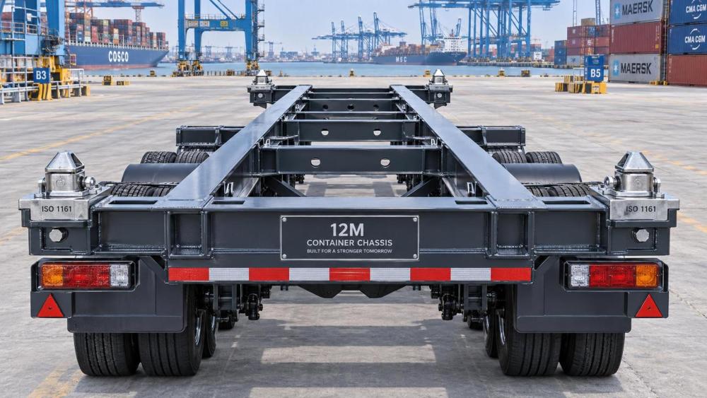
The primary load-bearing structure of a 12m skeletal container chassis consists of longitudinal beams (typically I-section or box-section), crossmembers, and end frames. While nominal section modulus and yield strength are routinely specified, their relevance depends entirely on how loads are transferred across the assembly. A chassis with high-strength steel longitudinal beams but widely spaced, thin-gauge crossmembers may exhibit localized buckling under concentrated container corner loads — especially at the rear axle zone where bending moments peak during braking or grade climbing. Conversely, over-engineered crossmembers add dead weight without proportionally increasing usable payload, directly reducing fleet efficiency metrics like ton-kilometers per liter of fuel.
More critical than individual component specs is the continuity of the load path. Welded joints between longitudinal beams and crossmembers must resist both shear and moment transfer; inconsistent weld penetration or mismatched filler metal tensile properties can create preferential fatigue initiation sites. ISO 1496-1:2023 specifies minimum static test loads for container handling equipment but does not mandate fatigue cycle requirements for chassis frames operating in high-frequency terminal environments. In practice, chassis subjected to >500 container lifts per week show measurable weld toe cracking after 18–24 months if joint detail design prioritizes fabrication speed over stress concentration mitigation.
Frame stiffness — particularly torsional rigidity — also dictates how evenly twist locks engage. A flexible frame allows differential vertical deflection between front and rear lock positions during container placement. This leads to partial engagement, where only two or three of four corner locks fully seat, transferring disproportionate load through fewer points and accelerating wear on locking mechanisms and container corner castings.
Twist Lock Configuration: Geometry, Clearance, and Engagement Sequence
Twist locks serve as the sole mechanical interface between chassis and container. Their configuration — number, location, actuation method, and geometric alignment — determines whether applied load is distributed across all eight container corner castings (four per end) or concentrated on fewer points. Standard ISO 1161-compliant 12m chassis use four twist locks: two forward, two aft, aligned with container corner fittings at 40ft spacing. However, lock height tolerance relative to chassis deck level, combined with container bottom plate deformation under load, means actual contact force distribution varies significantly.
Locks mounted on adjustable pedestals allow fine-tuning of vertical position during maintenance but introduce another variable: pedestal bolt preload consistency. Field measurements from three major European port operators (reported in *Port Technology International*, Q2 2023) found that 37% of inspected chassis had at least one pedestal bolt with torque deviation >25% from specification — leading to up to 40% reduction in effective load sharing among locks on that axle group.
Manual vs. automatic actuation introduces further divergence. Manual locks rely on operator judgment for full rotation; incomplete engagement leaves the lock in a “partially twisted” state, reducing shear resistance by up to 60% compared to full engagement (per DNV GL Class Notes Pt.6 Ch.12, 2022). Automatic systems eliminate human error but require precise synchronization — if front locks engage 0.3 seconds before rear locks during container lowering, transient unbalanced loading occurs, inducing cyclic stress in the frame’s mid-section.
Interaction Effects: Where Frame and Locks Converge
The most consequential capacity limitations arise not from either subsystem alone, but from their interaction. Consider lateral stability during sharp turns: a stiff frame resists roll but transmits higher lateral forces to twist locks. If lock housing welds lack sufficient throat thickness or if lock body material hardness falls below HRC 38 (per ASTM A354 Grade BD), plastic deformation accumulates after repeated events. Once lock housing deforms by >0.15mm, lock rotation becomes inconsistent, increasing the probability of false “locked” indication — a documented root cause in two near-miss incidents reported to the European Union Agency for Railways (ERA) in 2022.
Similarly, thermal expansion differences between chassis frame (typically ASTM A572 Gr.50) and twist lock components (often forged 4140 steel) affect clearance during extended operation in desert climates (>45°C ambient). Without compensatory design margins, lock bodies may bind in housings, preventing full disengagement during container offloading — a condition requiring manual intervention and delaying turnaround time by 8–12 minutes per cycle, according to terminal productivity audits conducted by PortIQ in 2024.
Evaluation Criteria for Technical Assessors
When reviewing chassis specifications or conducting factory acceptance tests, technical evaluators should prioritize verifiable evidence over declared ratings:
- Frame documentation: Request full FEA reports showing stress distribution under ISO 1496-1 test load cases (including 1.25x static load + 0.5g vertical shock), not just maximum Von Mises stress values. Pay attention to stress concentrations at crossmember-to-longitudinal weld toes and at suspension mounting brackets.
- Twist lock traceability: Verify batch-specific hardness testing records for lock bodies and housing welds. Confirm that lock actuation force curves (measured across full temperature range −20°C to +60°C) meet EN 12642-C requirements for retention force consistency.
- Interface validation: Insist on witnessed load testing using actual ISO containers — not simulated masses — with strain gauges placed at all four lock locations and mid-span frame sections. Discrepancies >10% between theoretical and measured load sharing indicate frame flexibility or lock alignment issues.
Real-world capacity is always lower than theoretical capacity. The gap depends on how well frame design accommodates operational variability and how precisely twist lock configuration maintains consistent, full engagement across environmental and usage conditions. Evaluators who treat chassis as a static structure with fixed load limits overlook the dynamic system behavior that defines safe, reliable service life.
For those evaluating structural integrity and interface reliability in 12m applications, the skeletal container chassis page provides dimensional drawings, material certifications, and third-party test summaries aligned with ISO and EN standards — supporting deeper technical review of frame geometry and twist lock integration.
Related News
Related News
- 00
0000-00
How port machinery systems reduce container handling bottlenecks - 00
0000-00
How smart port logistics systems reduce container dwell time - 00
0000-00
How transport equipment intelligence analysis identifies bottlenecks - 00
0000-00
How rail technology advancements are reshaping signaling standards - 00
0000-00
What is driving growth in the global EMU market size?
Weekly Insights
Stay ahead with our curated technology reports delivered every Monday.