Selecting Abrasion Control Systems for High-Wear Mining Transfer Points





At a high-wear mining transfer point, the right abrasion control system is rarely the one with the hardest liner on paper. A transfer chute may experience large lump impact at the inlet, fine-particle sliding wear through the spoon, material build-up around dead zones, and accelerated erosion where the stream changes direction. Treating all of those conditions with one lining material often creates a costly maintenance cycle rather than a durable solution.
Effective abrasion control mining starts with a clear separation of wear mechanisms. Technical selection should connect the material being handled, the way it enters and leaves the chute, the condition of the conveyor system, and the practical limits of installation and maintenance. The purpose is not simply to protect steelwork. It is to maintain controlled material flow, reduce spill and dust generation, and avoid shutdowns caused by worn-through chutes, damaged support frames, or inaccessible liners.
Start with the transfer point, not the liner catalogue
A useful evaluation begins by mapping where and how the transfer point is failing. “High wear” is too broad to guide a material choice. The same ore can cause impact damage in one zone and sliding abrasion in another. The evaluation should identify the material path from the loading conveyor to the receiving belt, including the point of first contact, any change in direction, the discharge trajectory, and areas where material decelerates or accumulates.
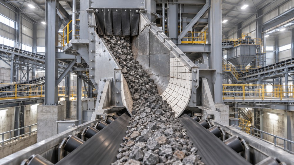
At the feed inlet, the main issue may be impact energy from large particles. In the chute body, it may become gouging abrasion as material slides along a surface under pressure. At a bend or rock box, particle-on-particle interaction may be more desirable than direct contact with a liner. At the discharge, poor stream control can cause off-centre loading, belt damage, carryback, and skirt leakage even when the chute itself appears well protected.
For this reason, a reliable abrasion control mining assessment uses the transfer point as a system. The liner, chute geometry, loading arrangement, sealing system, belt support, and maintenance method must be reviewed together. Replacing a failed plate with a more wear-resistant plate can extend liner life, but it will not correct an unstable material stream or a chute design that forces abrasive material into a sharp, high-velocity turn.
Define the dominant wear mechanism in each zone
Material hardness matters, but it is not sufficient on its own. Size distribution, moisture, particle shape, feed rate variation, and the presence of tramp metal can alter the type of damage a liner receives. Sharp, angular particles may cut and gouge. Fine, dry material can erode surfaces where velocity is high. Wet or sticky material can build up, changing the flow path and concentrating wear in unexpected areas.
The table is not a substitute for inspection. It is a way to prevent a common specification error: selecting a single liner grade for the whole chute because it simplifies procurement. Zoned design usually creates better lifecycle value. The most severe impact areas may need a different solution from long sliding sections or low-impact walls.
Compare lining materials by their operating role
Several liner categories can be appropriate in mining transfer points. None is universally superior. Their value depends on whether they are exposed to impact, sliding abrasion, erosion, noise, vibration, or material adherence.
Wear-resistant steel plate
Hardfaced or abrasion-resistant steel liners are widely used for sliding wear zones because they provide a robust surface and can be fabricated into chute structures. They are often a practical choice where the service team needs a familiar repair method and where dimensional rigidity is important. Their limitations become apparent when severe impact causes cracking, when geometry encourages concentrated wear, or when replacement requires extensive welding inside a confined chute.
Steel selection should include plate thickness, mounting arrangement, backing support, and the effect of heat input if on-site welding is expected. A liner that is wear-resistant but poorly supported can deform or loosen under impact. Likewise, a thick plate may protect the chute wall while adding enough weight to make safe replacement difficult.
Rubber and rubber-backed liners
Rubber-lined systems can absorb impact, reduce noise, and protect structures from repeated particle strikes. They are commonly useful where material is dropped onto an impact zone and where shock isolation matters as much as abrasion resistance. Rubber is not the preferred answer for every aggressive sliding application, particularly where sharp, high-pressure material continuously cuts across the surface.
When specifying rubber-based protection, assess the likelihood of tearing, the maximum lump size, the fastening design, and whether trapped material can work behind liner edges. Rubber often performs best when it is part of a controlled loading arrangement, not when it is expected to compensate for uncontrolled impact from excessive drop height.
Ceramic-lined components
Ceramic liners can provide strong resistance in severe sliding or erosive wear zones, especially where relatively fine abrasive material travels at speed. They are frequently considered for pipes, chutes, bends, and localized high-wear regions. However, ceramic solutions require careful matching to impact conditions. A hard wear face without adequate energy absorption or structural backing may be vulnerable where large rocks strike directly.
The evaluation should consider tile or module attachment, edge protection, joint exposure, and the consequence of a damaged section. Ceramic-lined assemblies are often most effective when installed in a location with predictable material flow rather than at a chaotic primary impact point.
Polyurethane and engineered polymer liners
Polyurethane and other engineered polymers can be valuable where impact, noise reduction, and material release must be balanced. Some applications benefit from their resilience and lower friction characteristics. Their suitability depends on the material temperature, chemical exposure, cut resistance, and the degree of direct impact. They should not be selected solely because they are lightweight or easy to handle; severe sharp-particle gouging can exceed their useful range.
Rock boxes and material-on-material protection
In some chutes, the most durable wear surface is a controlled layer of the bulk material itself. A rock box or engineered ledge can reduce direct wear on the structure by allowing material to form a sacrificial bed. This approach can be highly effective when the material stream is stable and the geometry supports consistent retention.
It is less suitable when material is sticky, highly variable, or prone to choking. A design that relies on a stable material bed can become a blockage point if flow conditions change. It also needs sufficient access to inspect and clear abnormal build-up.
Geometry can matter more than material grade
Transfer-point wear often exposes a flow problem rather than a liner problem. Excessive drop height, abrupt changes in direction, narrow throat sections, and poorly positioned impact surfaces raise velocity or force the stream into local contact points. This causes wear to concentrate in a small area and can lead to recurring failures even after premium liners are installed.
A well-designed chute guides the material instead of repeatedly stopping and redirecting it. The aim is controlled acceleration, controlled deceleration, and centred loading onto the receiving belt. This reduces liner wear, but it also improves downstream operating conditions: less belt mistracking, less skirt leakage, and fewer dust escape paths.
Technical evaluators should review the transfer arrangement under normal and upset conditions. Feed rates are not always steady. Large lumps may arrive intermittently, moisture can change the material trajectory, and a partially loaded belt can behave differently from a fully loaded one. A design that works only at nominal flow may create high wear during the operating conditions that most need resilience.
Assess the entire interface with the conveyor
Chute wear control cannot be separated from conveyor protection. The receiving belt needs to be supported through the loading zone so it can maintain a stable troughed profile under impact. If the belt sags between supports, skirt seals will wear unevenly and material will escape. Operators may then tighten the seals excessively, accelerating belt cover wear and increasing friction.
The discharge stream should also land in the belt’s direction of travel as closely as practical. A stream with a large lateral or opposing velocity component can abrade the belt, push material toward one side, and create uneven loading. In this situation, replacing chute liners alone may protect the steelwork while allowing the more expensive conveyor problem to continue.
Dust control should be evaluated at the same time. High internal velocity, air entrainment from falling material, and gaps around worn liners can make dust containment difficult. Abrasion-resistant components that create steps, exposed fasteners, or irregular internal surfaces may interfere with flow and collect fines. The best arrangement balances wear life with a smooth, maintainable flow path.
Do not ignore mounting and replacement design
A liner can have excellent wear properties and still be a poor selection if it cannot be safely inspected or changed. High-wear transfer points are commonly located in constrained areas where access is restricted, visibility is limited, and shutdown windows are short. The practical maintenance question is not simply how long the liner may last; it is what must happen when it reaches its service limit.
Check whether liner sections can be removed through existing access doors, whether lifting points are available, and whether fasteners can be reached without entering hazardous positions. Consider the failure mode of the mounting system as well. Bolts, studs, welds, and retaining bars can become wear points or can loosen under vibration and impact. Flush or protected fasteners may preserve flow, but they must remain serviceable.
Modular liners can reduce replacement effort because only the locally worn section needs to be changed. This is useful where wear is concentrated and predictable. Larger plates may be more economical where the wear pattern is broad and uniform. The appropriate choice depends on the expected wear map and the maintenance constraints, not on a general preference for either modularity or simplicity.
Use lifecycle cost, but make it operational
Initial liner price is a weak decision measure for a critical transfer point. Lifecycle cost should include fabrication work, installation time, access requirements, the duration and frequency of planned shutdowns, risk of unplanned failure, and related damage to belts, idlers, chutes, or dust systems.
A lower-cost liner can be appropriate in a lightly loaded zone with easy access. In a critical bottleneck, a more durable system may justify its higher installed cost because it reduces exposure to emergency maintenance. The point is not to assume that the longest-lasting material is always economical. Over-specification can add cost, complexity, and replacement difficulty in zones where wear is moderate.
When comparing proposals, ask suppliers to define their assumptions about feed size, material characteristics, impact location, operating hours, and access constraints. A proposal that does not state those assumptions is difficult to compare fairly. It may be based on a wear mechanism that is not dominant at the actual transfer point.
A practical selection sequence
- Document the failure pattern. Record worn-through locations, cracked liners, loose fasteners, build-up zones, belt damage, and spill points. Photographs during shutdown and observations during operation should be considered together.
- Map material flow. Identify where material first strikes, slides, turns, settles, and exits. Separate impact, sliding, and erosion zones instead of treating the chute as one surface.
- Define operating variability. Include normal feed, peak loading, oversized material, moisture changes, and likely upset conditions.
- Screen materials by zone. Compare steel, rubber, ceramic, polymer, and material-on-material arrangements against the specific mechanism in that location.
- Review geometry before finalising liners. Correct unnecessary drop height, abrupt turns, and unstable loading paths where feasible.
- Test maintainability. Confirm access, lifting, fastener reach, isolation requirements, and the replacement method before approving the design.
- Set inspection triggers. Define observable conditions that prompt inspection, such as exposed backing steel, liner movement, worsening spillage, abnormal noise, or recurring belt damage.
Common decisions that create repeat failures
One recurring mistake is specifying a hard liner everywhere. Hardness helps against certain forms of abrasion, but a primary impact zone may need resilience and structural support before it needs an extremely hard face. Another mistake is replacing the visible worn section without investigating why the wear concentrates there. The root cause may be a stream trajectory, a blocked flow path, or a change in feed characteristics.
It is also risky to evaluate liner life in isolation. A long-lasting liner that increases hang-up, creates dust leaks, or makes belt maintenance harder can raise the total operating burden. Conversely, a component with a shorter replacement interval may be rational when it is inexpensive, accessible, and deliberately protects more critical equipment.
For mines, bulk terminals, and other continuous material handling operations, transfer-point reliability is part of the wider logistics chain. TC-Insight’s coverage of bulk material handling reflects this connection: chute protection is not merely a maintenance detail, but one of the conditions that allows high-volume transport systems to run predictably.
Frequently asked questions
Should impact liners and sliding liners be specified separately?
Usually, yes. Impact and sliding abrasion impose different loads on the protective surface. Separating the zones allows the system to use impact absorption where material first lands and stronger sliding-wear resistance where the flow becomes established.
When is ceramic lining a poor choice for a transfer point?
It is a poor fit when large, unpredictable lumps strike directly on the ceramic surface without suitable backing or impact protection. Ceramic is generally better suited to controlled, high-abrasion flow zones than unstable primary impact locations.
Can a better liner solve conveyor spillage?
Only when worn chute surfaces or failed liner joints are the direct cause. Spillage often also involves belt support, loading alignment, skirt sealing, and air movement. Those conditions should be evaluated before treating the liner as the sole remedy.
What should be inspected before replacing a worn chute liner?
Inspect the surrounding structure, liner mounting, material trajectory, feed size changes, build-up points, receiving-belt condition, and access limitations. Replacing the component without understanding the failure pattern can reproduce the same wear rate.
Related News
Related News
- 00
0000-00
What determines port crane intelligence pricing for terminal upgrades? - 00
0000-00
Rail equipment intelligence in Southeast Asia is reshaping fleet investment - 00
0000-00
Selecting Abrasion Control Systems for High-Wear Mining Transfer Points - 00
0000-00
Which rail engineering standards govern a new freight line design? - 00
0000-00
Can Digital Intelligence Increase Terminal Throughput Without New Equipment?
Weekly Insights
Stay ahead with our curated technology reports delivered every Monday.