
Five Bottlenecks That Extend Bulk Transport Turnaround Time—and How to Remove Them





Turnaround time starts slipping long before a vessel, railcar, truck, or hopper reaches the departure point. The visible delay at discharge is often the accumulated result of unstable feed, poorly matched transfer equipment, blocked work fronts, maintenance work that arrives too late, or release decisions made with incomplete information. Bulk transport turnaround time improvement begins by tracing the material path as a connected operating cycle rather than treating each delay as an isolated event.
A useful first distinction is between slow throughput and lost time. A conveyor running below its design rate may still produce a predictable cycle. Lost time appears when the system repeatedly stops, waits, clears, restarts, or rehandles material. These interruptions are especially damaging because they spread across upstream loading, downstream storage capacity, mobile equipment availability, and dispatch windows. Removing the five bottlenecks below requires observing where time is consumed between the first tonne loaded and the final tonne discharged.
1. Unstable Loading Feed Creates Delays That Travel Downstream
Loading equipment is often judged by its rated capacity, yet rated capacity says little about whether the feed is steady. A reclaim hopper, feeder, shovel, wagon tippler, or ship loader can have sufficient peak output while still sending large surges and gaps into the transport line. The immediate result may be spillage, belt tracking problems, belt scale fluctuations, feeder trips, or repeated manual intervention. Farther downstream, those disturbances force receiving equipment to wait for material, then absorb a surge it was not configured to handle.
Material behavior changes the diagnosis. Fine, dry material can flood through a gate and overwhelm a belt; damp fines may bridge in a hopper and produce an apparently random stop-start flow. Large lumps, foreign objects, and frozen agglomerates cause a different pattern: brief high loads, jams at chutes, and irregular feeder torque. Treating all three conditions as a generic “low loading rate” leads to ineffective adjustments.
Start by recording the loading cycle at short intervals: feeder speed, belt loading, chute blockage events, hydraulic or motor load, and periods when the line is ready but receives no material. Compare this record with the nominal loading schedule. A stable average rate with frequent zero-flow intervals points to feed continuity rather than total capacity.
- Set feeder control around a workable belt loading range, not the highest possible feeder speed. Running at the limit leaves no room to absorb normal variation in moisture, particle size, or incoming truck dumps.
- Inspect hopper geometry and gate opening where bridging occurs. A larger opening alone can worsen rat-holing if material continues to flow only through a narrow central channel.
- Use a buffer bin or surge section only when the rest of the line has usable spare capacity. A buffer that is never properly replenished merely shifts the waiting point.
- Separate oversize removal from routine feeding. Repeatedly stopping a high-volume line to deal with occasional large pieces is a poor substitute for screening, grizzlies, or a defined rejection path.
Loading stability should be verified during the least favorable material condition, not only during clean, dry product runs. A control setting that looks efficient in one shift can cause persistent interruptions after rainfall, blending changes, or a different source material is introduced.
2. Transfer Points Restrict the Whole Conveying Route
Conveyors are frequently blamed for low transport performance, but the limiting point is often a chute, skirt section, diverter, or receiving pulley. A transfer point can pass material under light load and still fail during a continuous run because the stream enters off-center, strikes a wear surface, generates dust, or builds a shelf that gradually narrows the chute. The belt then carries uneven load, mistracks, and triggers a sequence of corrections that consumes far more time than the initial restriction.
Chute condition must be examined as a flow problem rather than a sheet-metal condition. Wear liners, hood shape, spoon trajectory, internal ledges, and the material’s moisture and particle distribution all affect whether material remains moving. A transfer designed around one ore, coal grade, aggregate size, or moisture range may behave poorly when the blend changes. Installing thicker liners improves wear life but can unintentionally reduce the available flow area if the original clearance was already tight.
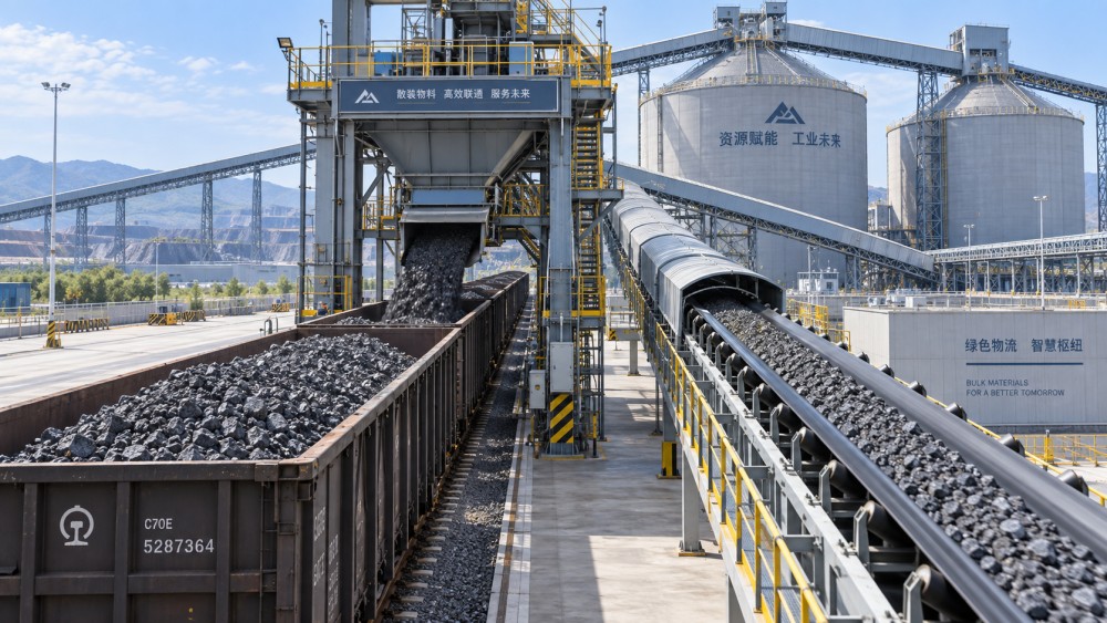
Look for physical evidence during planned inspections: polished impact zones, accumulated fines at dead corners, fresh spillage on one side, uneven skirt rubber wear, and material packed beneath idlers. Each points to a different correction. A polished sidewall may show that material is striking too early; packed material under the belt often indicates inadequate sealing or a misdirected stream; repeated buildup at a diverter may reveal a transition angle unsuitable for sticky material.
Correcting the transfer point generally follows a sequence. First restore the intended material path and clear accumulated deposits. Then confirm that the receiving belt has enough central loading length for the stream to settle before it reaches the next transition. Finally, tune skirt sealing and dust extraction after the stream is centered. Tightening skirt rubber against a badly loaded belt can increase drag and accelerate belt damage without solving spillage.
3. Queueing and Release Logic Leave Equipment Waiting for Permission
A transport asset can be mechanically available and still lose its cycle because the next location is not ready. Common examples include a loaded truck waiting for a tippler bay, an empty rail set held outside a loading zone, a conveyor stopped because the receiving stockpile is near its limit, or a vessel unloading sequence paused while a downstream route is switched. These delays are often described as scheduling issues, but the practical cause is usually a mismatch between actual process status and the release rule.
Static schedules are vulnerable when cycle times vary. A route that is normally clear may remain occupied after a chute blockage, belt clean-up, sampling hold, grade change, or delayed inspection. Releasing the next movement according to the clock then creates a queue in the least flexible area. Once vehicles, railcars, or mobile machines are stacked in a shared approach, recovery becomes slower because repositioning itself consumes capacity.
Use status conditions that reflect physical readiness. A destination should be considered ready only when it has confirmed space, an available route, functional containment, and no unresolved interlock or work permit. Likewise, loading should not begin merely because the next unit has arrived; the full route through discharge must have a credible path. This does not require complex automation in every operation. A disciplined shared status board, clear radio protocol, and a single current queue can remove many avoidable waits when information is otherwise fragmented.
Measure Queue Time Separately From Processing Time
A cycle report becomes misleading when all elapsed time is assigned to loading or unloading. Split the record into arrival, waiting for access, positioning, active loading or discharge, verification, departure clearance, and actual departure. The distinction matters. If active discharge is fast but departure clearance is slow, increasing discharge capacity will not improve turnaround. If positioning consumes excessive time, the issue may be traffic layout, spotting accuracy, visibility, or the order in which lanes and routes are released.
Grade segregation needs particular care. Holding material to protect quality is justified when routes, bins, or transport units could contaminate the next parcel. Yet broad “wait until clear” instructions can leave large capacity idle. Define the exact boundary: which transfer path must be emptied, what residue is acceptable, whether a flush quantity is needed, and who confirms completion. Ambiguous release criteria create conservative delays because no one can confidently authorize the next movement.
4. Maintenance Is Triggered by Failure Instead of the Earliest Useful Signal
Many turnaround delays are caused by small defects that were visible earlier: a belt beginning to wander, a bearing temperature rising under load, a feeder drive drawing unusual current, a loose scraper leaving carryback, or a chute liner worn through at one impact point. None necessarily stops the process immediately. Left unattended, each can become an emergency intervention that blocks the route at the worst possible time.
Maintenance priorities should follow operational consequence, not only component age. A minor defect on a redundant conveyor may be manageable for a short period. The same defect on a single route to the loading point can disrupt every subsequent activity. Criticality therefore depends on redundancy, access time, isolation requirements, spare availability, and whether the component can be repaired while the process is stopped for another planned reason.
Condition observations are most valuable when paired with operating context. High motor current during a heavy material run is not automatically a fault; the same current at ordinary feed may indicate resistance, buildup, or mechanical drag. A hot bearing reading should be compared with its own prior pattern, nearby components, ambient conditions, and load. Single readings invite unnecessary intervention, while repeated trends support planned action before availability is lost.
- Assign clear action thresholds for recurring signals such as belt misalignment trips, scraper adjustments, abnormal vibration, and blocked chute alarms.
- Keep route-critical wear parts and common failure items identified by location and fitment, including liners, idlers, sensors, pull-cord switches, seals, and coupling elements.
- Plan inspection access around the actual stoppage window. A short planned hold is wasted when covers, permits, lifting arrangements, or replacement parts are not ready.
Repeated resets are a warning sign, not a productivity tactic. Restarting after an alarm without recording the cause can keep material moving for a few minutes while increasing the likelihood of a longer failure later in the shift.
5. Discharge Is Limited by Material Release and Residual Clean-Out
Discharge bottlenecks are easy to underestimate because the transport unit has already arrived at its destination. Yet slow gate opening, incomplete emptying, carryback, blocked receiving hoppers, and residue checks can turn the final stage into the longest part of the cycle. The correct remedy depends on whether material is physically reluctant to leave, the receiving system cannot accept it, or the process requires extra cleaning before the unit can return.
Bulk material does not discharge uniformly. Free-flowing product may clear quickly but create dust and impact problems if released too rapidly. Cohesive or moist material may adhere to walls, hang in corners, or form arches above gates. Fine material can compact after vibration and transport, particularly where water enters open vehicles or material rests for extended periods. A slower gate operation is not always the problem; opening a gate too aggressively can overload the receiving belt and create a larger stoppage downstream.
Observe the discharge pattern rather than judging only the elapsed time. Material remaining at the front, center, or rear of a wagon, truck body, or hopper indicates different causes. Uniform residue suggests adhesion or surface condition. A persistent central mass suggests poor flow geometry or bridging. Material left near a gate may point to incomplete opening, obstruction, or a lip that catches fines. Cleaning methods should match the source of residue, with attention to whether water, vibration, liners, coating condition, or material conditioning is altering release behavior.
Close the Cycle With a Usable Return State
Fast discharge does not produce a fast turnaround if the unit cannot be released. Gates must be secured, sensors reset, residual material managed according to the next load requirement, and the departure route confirmed. Build these steps into the discharge sequence instead of treating them as afterthoughts. A unit that reaches the exit lane and then waits for inspection, paperwork, route clearance, or corrective clean-out still occupies valuable space.
For bulk transport turnaround time improvement, focus daily review on the longest recurring interruption, its location, its trigger, and the time needed to recover. The most productive change is often a modest correction at the point where a small delay repeatedly forces the entire flow to wait.
Related News
Related News
- 00
0000-00
Freight railway technology insights for reducing unplanned downtime - 00
0000-00
How rail logistics in the Middle East is reshaping freight corridor capacity - 00
0000-00
What railway rolling stock market analysis reveals about fleet demand - 00
0000-00
How axle load limits shape mainline railway freight capacity - 00
0000-00
How to match ship loaders to bulk terminal throughput targets
Weekly Insights
Stay ahead with our curated technology reports delivered every Monday.