
How Conveyor Belt Transport Moves Bulk Cargo Through a Port Terminal





Conveyor belt transport moves bulk cargo through a port terminal by linking receiving equipment, storage areas, and dispatch points into a controlled flow. Coal, grain, or ore lands on a supported moving belt, travels along a selected route, and discharges through a chute onto another conveyor or into storage or loading equipment. Each belt handles one part of the journey; feeders, transfer points, and control systems keep those parts working together.
The route changes with the terminal’s purpose. An import terminal generally moves cargo from a vessel toward stockpiles, silos, or inland transport. An export terminal receives material from rail wagons, trucks, or other conveyors and directs it toward a shiploader. Storage separates these activities in time, allowing vessel handling to continue when inland deliveries or dispatch rates fluctuate.
Following the cargo from the berth
At an import berth, a grab unloader deposits batches into a receiving hopper, while a continuous ship unloader delivers a steadier stream through its discharge arrangement. The downstream conveyor requires a controlled feed in either case. A hopper absorbs short fluctuations, and a feeder meters material onto the belt at a rate the route can accept.
A hopper has finite capacity. If grabs deliver cargo faster than the feeder removes it, the level rises until unloading must pause. If feeding stops between grabs and the hopper empties, the belt runs partly unloaded. This difference explains why an unloader’s maximum handling rate does not automatically become the terminal’s sustained transfer rate.
After leaving the berth, cargo passes through transfer towers where chutes connect successive conveyors. Diverter gates select destinations such as a stockyard, covered store, or silo. The control system must confirm the selected route before releasing material: a running conveyor alone does not prove that its discharge path is available.
In a stockyard, a stacker places material in a planned pile. A reclaimer later retrieves it and feeds an outgoing conveyor. Some terminals use combined stacker-reclaimers, while others separate the machines. Export flows continue toward a shiploader; inland dispatch routes terminate at facilities such as rail loading bins or truck loading stations.
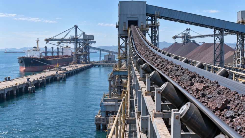
What carries the load along the belt
A belt conveyor consists of an endless belt running around pulleys, with a drive providing motion and idlers supporting the carrying and return runs. On many bulk routes, carrying idlers form the belt into a trough. This shape increases the material cross-section and helps contain cargo, although the loading arrangement still needs space at the edges to prevent spillage.
The belt’s internal reinforcement carries tension, while its covers withstand contact with cargo and conveyor components. Fabric-reinforced and steel-cord constructions serve different tension, length, and installation requirements. Cover selection addresses abrasion, cutting, temperature, and relevant fire or material compatibility requirements. A belt suitable for sharp ore is not automatically suitable for handling food-grade grain.
A take-up maintains the tension needed for traction and accommodates changes in belt length. Too little tension can allow slipping at the drive pulley or excessive sag between supports. Excessive tension increases stress on the belt, splices, and components. Pulley diameter, belt construction, and splice design therefore belong to the same mechanical assessment.
Inclines introduce another constraint. Material must remain stable on the moving surface through starts, stops, and normal operation. Loose cargo can slide or roll backward if the slope exceeds what its properties and belt surface permit. Steeper routes require an appropriate conveying arrangement, such as a specially configured belt system, rather than simply increasing drive power.
Throughput is a property of the complete route
A conveyor’s mass carrying rate follows three linked quantities: the loaded cross-sectional area, belt speed, and cargo bulk density. Increasing any one increases the calculated mass rate, provided the other conditions remain valid. Belt width alone gives an incomplete picture because trough geometry, edge clearance, and the material’s shape on the belt determine the usable area.
Bulk density creates an important distinction between volume and mass. A belt carrying lighter material can reach its volumetric limit while transporting fewer tonnes per hour. A denser cargo places greater weight on the belt at the same loading profile. Material condition also matters: moisture, particle size distribution, and compaction can change density and feeding behavior.
Higher speed does not solve every capacity problem. It changes the discharge trajectory, increases demands on transfer chutes, and can worsen dust or material degradation. If a downstream conveyor, chute, or receiving machine cannot accept the flow, increasing the upstream rate produces accumulation rather than useful throughput.
The limiting stage sets the sustainable route capacity. A berth conveyor may have ample carrying capacity while a narrow chute restricts wet cargo. Elsewhere, a reclaimer’s recovery rate or a loading bin’s discharge cycle controls output. Capacity assessment therefore follows the cargo from its receiving point to its destination, including interruptions and equipment availability.
Transfer points determine whether cargo stays controlled
At a transfer, material leaves the head pulley and follows a trajectory into a chute. The chute must guide that stream onto the receiving belt in a suitable position and direction. Centered loading reduces the tendency to push the belt sideways. Matching the stream’s direction and speed more closely to the receiving belt reduces impact and sliding at the loading zone.
Large lumps require enough clearance to pass without bridging and adequate support where they land. Fine, wet material creates a different problem: it adheres to chute walls and progressively narrows the flow passage. Chute geometry and liner choice must address the actual cargo; a surface that resists abrasive wear does not necessarily resist sticky buildup.
Impact beds or impact idlers support the belt beneath the loading point. Skirting contains material while it settles into a stable profile, but excessive skirt pressure increases friction and wear. If the belt sags away from the seals, tightening them alone will not correct the underlying support problem.
Transfer design also influences particle damage. A long uncontrolled fall or repeated high-impact transfers can break friable cargo and generate additional fines. Those fines then affect dust generation, chute behavior, and cleaning demands farther along the route.
Different cargoes change the handling conditions
These characteristics can occur together. A cargo containing coarse lumps and wet fines requires both impact protection and resistance to blockage. Testing or examining representative material is more useful than selecting equipment from the commodity name alone. Seasonal moisture changes can explain why a route that handled one shipment smoothly struggles with the next.
Coordinating starts, stops, and changes of destination
For a normal start, downstream equipment generally starts before upstream feeding begins. This creates an available discharge path before cargo arrives. During a planned stop, feeding stops first, and the conveyors continue long enough to clear material where the operating arrangement permits. Emergency stops interrupt this sequence, so restarting can involve belts that remain loaded.
Interlocks connect the equipment into a working route. Belt speed detection identifies slipping or a stopped belt; chute blockage sensors detect accumulation; misalignment switches indicate excessive sideways movement. A downstream trip must stop or inhibit the upstream feed quickly enough to avoid overfilling the affected transfer.
Changing a diverter while material is flowing can send cargo to the wrong destination or trap it around the gate. Route changes need a sequence that accounts for material already travelling on the belts. Travel time matters on long conveyors: stopping the feeder does not immediately stop discharge at the far end.
Belt scales measure the passing mass flow, while other instruments track equipment condition. A low belt-scale reading might reflect reduced feeding, an upstream blockage, or an inaccurate measurement. Scale installation, calibration, and belt conditions affect measurement quality, so the reading needs to be interpreted alongside the state of the route.
Keeping dust, spillage, and carryback under control
Dust escapes most readily where cargo falls, accelerates, or displaces air. Enclosed transfers and extraction systems manage that release, while water-based suppression suits only cargoes and processes that tolerate added moisture. For grain and other combustible dusts, containment and housekeeping also relate to fire and explosion hazards; enclosure alone does not address those hazards.
Spillage has several distinct causes. Off-center loading can push material toward one edge. Overfeeding fills the belt beyond its stable profile. Damaged skirting leaks at the loading zone, while poor tracking shifts the belt away from its intended path. The location and timing of a spill help distinguish these mechanisms.
Carryback is material that remains attached after the belt discharges and travels onto the return run. It accumulates on idlers and beneath the conveyor, creating further tracking and cleaning problems. Primary and secondary cleaners remove residue at the discharge end, with their settings matched to belt condition and splice construction. Excessive cleaner pressure accelerates wear without necessarily improving cleaning.
Reliability comes from accessible, observable equipment
A seized idler, damaged splice, or deteriorating pulley lagging can interrupt an entire cargo route. Inspection access, safe maintenance platforms, and space to replace components influence how quickly faults are found and repaired. Guards protect moving parts, and maintenance requires isolation of hazardous energy, including stored tension and the possibility of material movement.
Condition monitoring helps distinguish developing faults from normal variation. Bearing temperature, vibration, drive current, and belt tracking provide different evidence. Rising power consumption at an unchanged cargo rate could indicate rubbing, seized rollers, buildup, or altered material conditions. The signal identifies a change; inspection establishes its cause.
Energy use also follows the physical route. Lifting cargo requires power, while rolling resistance, belt flexing, and mechanical losses add to demand. Variable-speed drives support controlled starts and rate adjustment, but reduced speed must still preserve a stable loading profile and effective transfers. A terminal conveyor works reliably when its feeding, movement, and discharge remain matched throughout the cargo’s journey.
Have questions about the global trade trends discussed here, or planning your expansion and supply chain strategy? Leave a message below and let the trade experts at TTC-Insight guide you.
We respect your privacy. Your information is strictly confidential.
Related News
Related News
- 00
0000-00
How public funding shapes the urban rail transit market - 00
0000-00
How do terminal operations systems coordinate crane scheduling? - 00
0000-00
Evaluating Skeletal Container Chassis Capacity for Loaded Boxes - 00
0000-00
How much outreach does a container terminal crane need? - 00
0000-00
Which rail safety technology standards apply to CBTC systems?
Weekly Insights
Stay ahead with our curated technology reports delivered every Monday.