
Designing Agricultural Port Loading Systems to Protect Grain Quality and Cut Spillage





Grain quality is often lost at the last few transfer points before a vessel is loaded. A system can meet a nominal loading rate and still create excessive breakage, dust clouds, hold contamination, or grain piles that must be trimmed by mobile equipment. The design target for agricultural port loading is therefore a controlled product path: grain should remain enclosed where practical, change direction gradually, land in the vessel with limited impact, and be measured well enough to keep the berth schedule predictable.
That objective starts with the actual grain stream rather than a conveyor catalogue. Wheat, maize, soybeans, barley, oilseed meals, and similar products differ in particle shape, bulk density, moisture sensitivity, dustiness, and tolerance to repeated handling. A loading arrangement designed around maximum belt capacity alone often overlooks the points where the material accelerates, strikes a hard surface, segregates, or escapes from the enclosure.
Start with the grain path and vessel-loading pattern
Map every movement from the final storage outlet to the cargo hold, including gates, feeders, conveyors, transfer towers, sampling points, weighing equipment, ship-loader boom conveyors, telescopic spouts, and discharge chutes. At each point, define the expected flow rate, drop height, belt speed, material depth, and whether the stream is full, partially loaded, or intermittent. The worst operating condition is frequently not the design throughput. It may be a low-rate topping-off operation, a partially closed slide gate, or the first material entering an empty hold.
The vessel arrangement changes the preferred loading geometry. A wide hatch with a shallow hold allows a broader, lower-energy discharge pattern than a narrow hatch leading to a deep hold. Cargo holds with internal structures require deliberate placement so grain does not build against ladders, frames, or hatch coamings. A fixed boom position may load rapidly near the center while creating a later trimming burden at the sides. A travelling ship loader, luffing boom, or telescopic loading spout provides more placement control, but only when its movement limits, interlocks, and cable management match the berth layout.
Do not treat hold filling as a visual task added after mechanical design. Define the loading sequence by hatch, hold zone, and target pile profile before selecting the final discharge equipment. This makes it possible to identify where a rotating chute, slew motion, telescopic spout, or controlled repositioning of the boom is justified. It also exposes conflicts between the desired loading pattern and clearance limits imposed by ship geometry, tides, railings, hatch covers, or fenders.
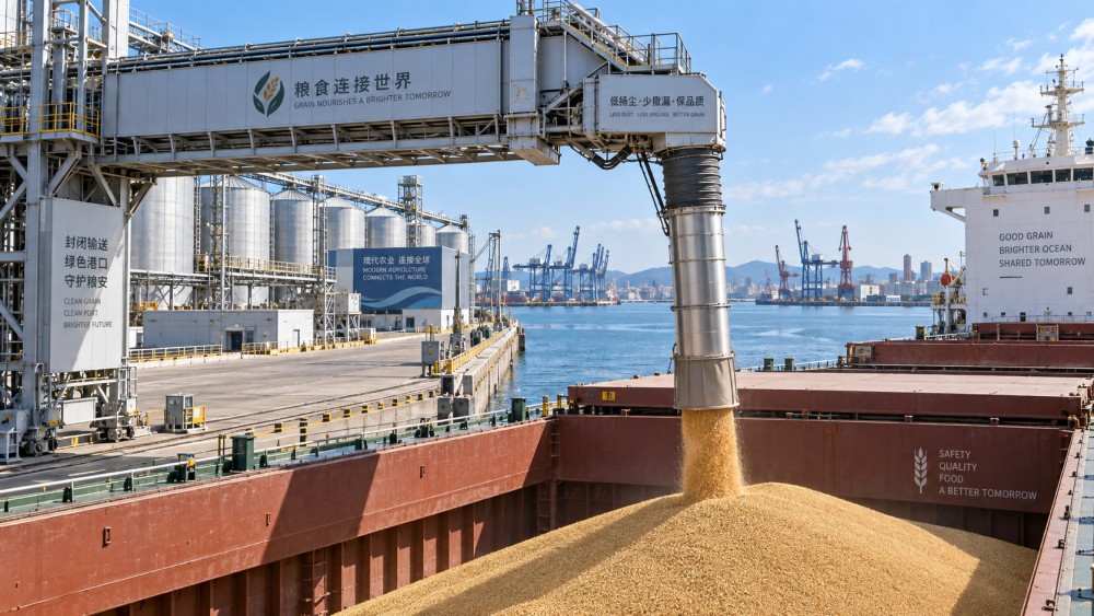
Containment begins before the ship loader
Visible grain loss at the berth is often traced to the ship-loader discharge, yet upstream transfer stations may be the larger source of dust and spillage. A well-designed enclosed conveyor route keeps the conveyed material centered on the belt and prevents air from carrying fines through gaps in covers and transfer housings. Covers alone do not solve the problem when a transfer chute creates a high-velocity jet or when the receiving belt is poorly loaded.
At a belt-to-belt transfer, the discharge trajectory should match the receiving belt direction and speed as closely as practical. Material that lands against the belt direction, or drops too far onto a fast belt, rolls and scatters toward the skirtboards. This creates recurring cleanup, accelerates belt-edge wear, and sends more dust into the enclosure. A transfer chute should guide the material instead of allowing it to free-fall through an oversized box.
Chute geometry deserves early engineering attention. Abrupt direction changes, sharp internal ledges, exposed bolts, and short-radius corners create impact points where kernels fracture and material accumulates. Grain held on a shelf can later release as a surge, upsetting downstream belt loading and creating a dust pulse. Wear liners are necessary in high-contact zones, but liner selection cannot compensate for a poor flow path. A hard liner may resist abrasion while increasing impact damage to fragile grain; a softer or low-friction surface may be better in locations where product preservation matters more than abrasive life.
Design transfer points for stable flow, not just passage
Material behavior varies with moisture, fines content, and storage history. A chute that flows cleanly with dry, free-running grain can bridge or retain material when a damp lot is introduced. Conversely, a chute opened too widely for a low-density product can allow the stream to spread and entrain air. The design review should include the expected range of bulk density and moisture condition, not a single representative value.
- Maintain a controlled stream: use curved or spoon-type chute sections where a substantial direction change is needed, reducing free-fall and keeping the stream compact as it approaches the receiving belt or vessel.
- Provide access where buildup is credible: inspection doors must open safely and give access to the surfaces that actually retain material, rather than only to the empty lower section of a transfer housing.
- Seal interfaces without making maintenance impractical: skirtboard seals, inspection doors, and conveyor covers need compression and alignment that can be maintained after vibration, thermal movement, and routine belt replacement.
- Control induced air: dust extraction points should be located around the zone where air is displaced or entrained, with sufficient enclosure volume to avoid drawing grain directly into the duct.
For dust collection, the relevant question is not simply whether a filter unit is included. Airflow must reflect the transfer geometry, enclosure leakage, incoming material rate, and the number of simultaneous transfer points. Excessive negative pressure can pull product from the transfer stream and increase internal wear. Too little capture allows dust to escape through joints, inspection doors, and the discharge opening. The system also needs a planned destination for collected dust that does not reintroduce it into clean grain without assessing its quality and contamination status.
Manage impact at the vessel interface
The final drop is the most sensitive location because it combines product impact, open-air dust release, wind exposure, and vessel movement. An open discharge from a boom conveyor may be adequate where the drop is short, grain is robust, wind exposure is limited, and the required hold distribution can be achieved without frequent repositioning. It becomes less suitable when the boom must remain high above the hatch, when dust control is a priority, or when fragile kernels are subject to repeated impact.
A telescopic loading spout reduces the uncontrolled drop distance by extending toward the growing grain pile. The lower outlet should maintain enough clearance to avoid burying, dragging, or striking the cargo surface as the vessel loader moves. A level sensor, cable-tension arrangement, or other position feedback may be used to manage this clearance, but sensor selection must account for dust, vibration, changing grain surfaces, and the risk of false readings during startup. Mechanical travel limits and a clear fallback operating mode remain necessary.
Some discharge arrangements use an inner material spout with an outer dust skirt. This can contain the air displaced as grain enters the hold, particularly when the skirt reaches near the pile surface. The skirt must be durable enough for contact and movement, while remaining light enough that it does not damage the cargo surface or interfere with the spout. A skirt that is routinely folded back or removed because it obstructs the loading sequence has little practical value.
Wind should be considered as a design condition, not an operational inconvenience. At exposed berths, crosswinds can deflect fine material far beyond a nominal discharge footprint. Enclosing the stream near the outlet, lowering the discharge point, and minimizing time spent with an empty spout over an open hatch reduce this exposure. Local wind limits and alarm logic should align with the mechanical capability of the loader, including boom positioning and safe stowage. The response to high wind should be defined in the loading procedure rather than improvised after product has begun to spill.
Capacity calculations need a quality constraint
Rated tonnage per hour is useful for berth planning, but it should not be the sole sizing basis. A loading line that reaches its peak rate only with high belt speed, aggressive gates, and unstable transfer flow may create enough grain loss or cleanup delay to reduce actual vessel turnaround. Establish a normal operating rate and a controlled lower-rate range, then verify that feeders, conveyor scales, chutes, dust control, and the ship-loader outlet remain stable across both conditions.
Surge capacity upstream of the ship loader is particularly valuable when vessel-side movements briefly slow the final discharge. Without buffering, a short stop can force upstream conveyors to stop under load. Restarting may release accumulated material through several transfer points at once, causing belt overloading and dust escape. With a suitable surge bin or controlled upstream sequence, the final loader can pause for hatch movement or repositioning without turning a local interruption into a line-wide upset.
That buffer must be assessed for grain residence time and cleanout. Grain left in a hopper, dead pocket, or idle conveyor can absorb moisture, retain dust, or mix with a later cargo grade. Flow-promoting devices should be selected carefully. Vibrators, air cannons, and mechanical agitators can restore flow in some applications, but they can also increase fines, disturb dust, or complicate cleaning if applied indiscriminately. A gravity-led bin geometry with accessible discharge zones is usually easier to manage than a complex hopper that depends on frequent intervention.
Automation should control deviations, not hide them
Automation is most useful when it maintains stable loading conditions and makes deviations visible early. Conveyor speed control, feeder regulation, belt scales, bin level instruments, and ship-loader position feedback can coordinate the material stream with the vessel-loading sequence. The controls logic should prevent a feeder from starting into a stopped downstream belt, restrict boom movements that would exceed safe operating envelopes, and manage gradual acceleration rather than abrupt starts that throw material from the belt.
Measurement quality matters at handover points. A belt scale may support loading control, but its reading can drift if belt tracking, idler condition, material profile, or zero calibration is neglected. Using a single instrument reading as the only indication of loaded quantity can cause avoidable disputes or poorly timed hold changes. The design should specify where measurement is used for process control, where it is used for reconciliation, and how its condition is verified during operation.
Alarm design also needs restraint. A crowded alarm list encourages acknowledgement without action. Prioritize conditions that affect grain loss, mechanical damage, dust escape, fire exposure, and vessel interface safety: blocked chute indications, belt drift, abnormal motor load, dust collector faults, spout travel limits, and loss of position feedback. Each alarm should lead to a defined response, whether that is controlled slowdown, immediate stop, inspection, or a transfer to local control.
Installation details often determine whether containment survives
Equipment drawings may show enclosed transfers and continuous covers, but installation tolerances can leave gaps at interfaces. Misaligned conveyor frames alter the material path. Incorrect skirtboard spacing can rub the belt or leave a route for material escape. A spout installed without allowance for structural deflection may bind during boom movement. These issues are easier to correct before commissioning than after grain dust has entered every joint and access space.
Commissioning should begin with dry functional testing of drives, interlocks, emergency stops, boom travel, spout movement, dust collection, and communication between equipment packages. Product trials then need observation at several rates, including startup, normal flow, reduced rate, stopping, and restart. Inspect belt tracking and carryback after the first sustained run, not only while belts are empty. Review the floor, enclosure joints, chute access doors, and vessel coaming area for evidence of escape. Fine dust patterns frequently reveal airflow problems that are not obvious from a control screen.
Maintainability should be built into the loading system before fabrication. Wear liners, seals, filters, idlers, scrapers, and spout cables all have replacement cycles. Safe access platforms, lifting points, isolation locations, and adequate clearance around inspection doors reduce the tendency to defer small repairs until they become chronic sources of spillage. Cleaning routes should keep recovered grain and dust separate where quality control requires it, and avoid placing drains, ledges, or inaccessible pockets where product can remain between cargoes.
A reliable agricultural port loading system is defined by consistent behavior across the whole loading cycle: controlled transfer, stable containment, deliberate cargo placement, and equipment that can be inspected before loss becomes visible at the berth. When those requirements shape the mechanical layout and controls philosophy from the beginning, throughput and grain protection reinforce each other rather than compete.
Related News
Related News
- 00
0000-00
Comparing bulk handling solutions by throughput reliability - 00
0000-00
What determines port crane intelligence pricing for terminal upgrades? - 00
0000-00
Rail equipment intelligence in Southeast Asia is reshaping fleet investment - 00
0000-00
Selecting Abrasion Control Systems for High-Wear Mining Transfer Points - 00
0000-00
Designing Agricultural Port Loading Systems to Protect Grain Quality and Cut Spillage
Weekly Insights
Stay ahead with our curated technology reports delivered every Monday.